top of page
Join
Forums
AI Support
Content
Articles
Field Guides
Programs
Videos
Terminology
Mental Fitness
Services
Gear
About
FAQ
Rewards
Why Truckroll
Work Together
More
Use tab to navigate through the menu items.
Search
Log In
Industry Videos
Play Video
Play Video
13:41
Don't Get Burned by MC4 Solar Connectors
MC4 Solar Connector Guide: Proper Connections, Cross-Mating Brands, & Spotting Fakes Learn how to connect an MC4 solar connector correctly and avoid costly mistakes on-site! In this video, we'll dive into everything you need to know about MC4 solar connectors, including whether you can cross-mate different brands and how to spot fake MC4 connectors. ======================================== Time Stamps ⏱ 00:00 MC4 connectors get bad press 00:30 What makes MC4 connectors problematic? 01:36 How to properly assemble an MC4 connector 03:56 MC4 crimp strength test 05:22 MC4 History 06:05 Staubli has a 50% market share, who has the other 50%? 08:05 Don't mix different manufacturers 08:26 Be cautious of fake and sub standard MC4 connectors! 09:27 Fire safety with PV panel installations 10:37 You can find guidance in the wiring regs 11:11 Scenarios for mixing connectors 12:35 The MC4 design has evolved with solar installations ====================================== #mc4 #solarinstallation #solarpanels
Play Video
Play Video
10:25
How Does the Power Grid Work?
The modern world depends on electricity. It’s a crucial resource, especially in urban areas, but electricity can’t be created, stored, and provided at a later time. The instant it’s produced, it’s used no matter how far apart the producer is from the user. And the infrastructure that makes all this possible is one of humanity’s most important and fascinating engineering achievements: the power grid. -Patreon: http://patreon.com/PracticalEngineering -Website: http://practical.engineering Writing/Editing/Production: Grady Hillhouse Tonic and Energy by Elexive is licensed under a Creative Commons Attribution License Source: https://www.youtube.com/watch?v=U6fBPdu8w9U This video is sponsored by NordVPN.
Play Video
Play Video
05:31
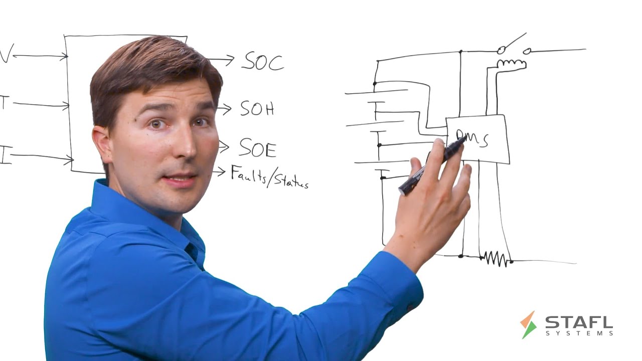
What is a Battery Management System?
Have you ever wondered how a Battery Management System works? Erik Stafl, President of Stafl Systems, walks you through the basics, starting with two primary purposes of a battery management system for a lithium-ion battery pack: providing safe and reliable operation. Topics Covered: Purpose of a BMS BMS Inputs BMS Outputs Current Sensors BMS System Diagram BMS Communication The Battery Management System takes a number of inputs, including voltage, temperatures, and current among other inputs. The BMS then runs algorithms to create a series of outputs including state of charge (the fuel gauge), the state of health, the safe operating envelope ™, and any faults the battery pack may have. Erik then describes how the BMS is used in a multi-cell application, using a system diagram. Learn more at https://staflsystems.com.
Play Video
Play Video
04:09
How Does Electricity Flow Through a Utility-Scale Solar Site?
The utility-scale solar segment installed 7.6 GWdc in Q2 2024 - a whopping 59% jump from last year, according to SEIA's latest Solar Market Insight Report. If you're one of the newer folks joining in the industry to help get solar projects online, welcome! It may be helpful to dive into something fundamental to getting more solar energy onto the grid and that’s how electricity actually flows through these massive PV systems. Understanding this process is crucial for solar professionals regardless of their role in the industry. In this excerpt from Utility-Scale Solar PV Fundamentals, HeatSpring instructor Andy Nyce breaks down the journey of electrons from sunlight to high-voltage transmission lines. Want to dive deeper? Check out Andy's Utility-Scale Solar Essentials course bundle. It's packed with foundational concepts and practical insights that'll give you a serious edge in the utility-scale solar segment. - https://www.heatspring.com/courses/utility-scale-solar-essentials
Play Video
Play Video
02:06
How to pull a transformer DGA oil sample | Maddox Industrial Transformer
This step-by-step guide will show you how to pull an oil sample from your transformer. For more information on transformer maintenance visit: https://www.maddoxtransformer.com/news/should-i-repair-or-replace-my-transformer *For educational purposes only, should be performed by qualified professionals* To pull an oil sample from your electrical transformer for analysis: Step 1: Tank pressure is relieved First, the tank is relieved of pressure. Most transformers have an operating pressure of around 2 PSI. Before an oil sample can be taken the vacuum/pressure gauge must read 0. The gas sample valve is opened to relieve the pressure. Step 2: Purging the drain valve The cap is then removed from the sample port, and the drain valve is opened to purge any moisture, dirt, or other contaminants before sampling. Some people also recommend removing the drain plug on the end of the valve and cleaning it, just in case there are contaminates stuck to the back wall of the plug, but that’s usually not needed. Step 3: Preparing the syringe Sample syringes are provided by the laboratory performing the analysis. The valve on the syringe has 3 positions. Position 1: Closed to hose Position 2: Closed to bleeder Position 3: Closed to syringe With the valve in the “closed to bleeder” position, the sample can be taken. Step 4: Pulling the sample In this example, a small piece of plastic hose is used as an adapter to connect the syringe to the sample port. The adapter is also purged before the sample is taken. The syringe is inserted into the hose, the drain valve opened and the syringe is filled to a little bit over the 50cc mark. Step 5: Evacuating air from the syringe After the sample is pulled, the air in the syringe is evacuated With the syringe in an upright position, and the valve closed to either the bleeder or the hose, the plunger is pushed up, forcing the air and a little bit of oil out until the 50cc mark is reached. Step 6: Packing the syringe back up With the valve in the closed-to-syringe position, the syringe is wiped clean of oil, and packed for shipment to the laboratory for analysis. Step 7: Cleanup The sample port cap is re-attached, and the excess oil is disposed of per EPA guidelines. Step 8: Re-pressurizing the tank Finally, the tank is re-pressurized with nitrogen, and closed. For more information or how to purchase an electrical transformer please visit: https://www.maddoxtransformer.com/ Timestamps: 0:00 Introduction 0:06 Tank pressure is relieved 0:21 Purging the drain valve 0:41 Preparing the syringe 1:00 Pulling the sample 1:22 Evacuating air from the syringe 1:36 Packing up the syringe 1:45 Clean-up 1:51 Re-pressurizing the tank
Play Video
Play Video
12:20
How to assemble and crimp Stäubli Original MC4 / MC4-Evo 2 solar power connectors | Best practice
PV installations are expected to endure safely for more than 25 years. Therefore, when it comes to wiring the PV system, the correct assembly and crimping with qualified tools is crucial. Follow the official step-by-step video tutorial through the assembly and crimping process for the Original MC4 / MC4-Evo 2 photovoltaic connectors. By using the Stäubli qualified assembly tools resp. certified crimping pliers and following the assembly instructions carefully you enhance the quality of the PV DC wiring and make sure it lasts. For more information: https://www.staubli.com/global/en/electrical-connectors/products/renewable-energy-solutions/tools-and-accessories.html? About Stäubli Stäubli stands for innovative mechatronics solutions in the electrical connectors, fluid connectors, robotics, and textile divisions. With over 6,000 employees, the company operates in 28 countries. In the renewable energy sector, Stäubli Electrical Connectors has set the industry benchmark with its MC4 connector portfolio based on the reliable MULTILAM contact technology. Active in this market for more than 25 years, Stäubli creates the basis for sustainable change and connections for life. www.staubli-renewable-energy.com #Stäubli #mc4 #crimping #tutorial #renewableenergy #theoriginalmc4 #solar#greenenergy #cleanenergy #solarconnector #solarconnection #connectorassembly #pv #bestpractice #pvdcconnector #pvconnector 0:00 Intro 1:25 Cable Preparation Cut the wire 2:04 Cable Preparation Strip the wire 2:41 Crimp Process Select the correct crimping pliers 3:07 Crimp Process Insert metal crimp contact 3:44 Crimp Process Align crimp contact 4:52 Crimp Process Visual inspection 5:42 Crimped wire terminal insertion into insulator body Identify and choose cable coupler 6:51 Crimped wire contact insertion into insulator body Insert crimped wire contact into insulator coupler 7:21 Crimped wire contact insertion into insulator body Inspection 7:51 Pre-tighten cap nut (optional) 9:11 Torque cap nut (mandatory) 10:36 Pre-tighten and torque cap nut Inspection 10:49 Connector mating and disconnection Connector mating 11:22 Connector mating and disconnection Connector disconnection
Play Video
Play Video
05:03
PV Electrical Testing: Test Setup
Initial test setup for electrical field testing a PV system during commissioning or O&M. Test setup for IV curve tracing and insulation resistance testing (IRT or Megger) inside the combiner box. Want more? Take the MW Design Course: https://www.heatspring.com/courses/megawatt-design?aff_id=am5riw
Play Video
Play Video
01:15
Challenges and Best Practices in the Solar Industry
At Fluke, we're asked about the best practices when it comes to installing and testing PV systems. Learn more about using Fluke tools in the solar industry. https://bit.ly/3C90NG1 Typically on an installation, you'll have several connections. You'll have your inverter connections, your combiner box connections. Best practice is to make sure that all of this is tight, connected, and your wire management is secure, that nothing can fall out. Best practices to have a technician using a clamp meter to make sure that you're not overloaded. So, having the essential tool like a clamp meter, or a high voltage clamp meter, to make sure that the strings for the inverter are not overloaded. It's important to use the right tools with the right cat ratings. Also, make sure you have the proper PPE gear on, which is your personal protective equipment. Good tools are essential on the job and also to ensure technicians go safely home to their families when their jobs are done.
Play Video
Play Video
17:00
5 Formulas Electricians Should Have Memorized!
Being a great electrician requires a strong knowledge of math. We use it daily from bending conduit, to figuring out what wire to pull, even simply counting light fixtures or circuits. But which formulas should we be more familiar with? In todays episode of Electrician U, Dustin explains the top 5 formulas every electrician should know. 🤘⚡️EU Learning System⚡️🤘 For Individuals --- https://electricianu.com/learning-system-for-individuals/ For Businesses --- https://electricianu.com/learning-system-for-businesses/ -Video courses on every side of the electrical trade (theory, code, safety, wiring, install, troubleshooting, leadership, and more) -Practice exams for 2017, 2020, 2023 code -YouTube videos categorized and searchable -Audio lessons -Forum -Business version has admin portal and ability to assign learning to technicians and monitor progress -Any business size from 2 techs to 2,000! 🎓💡CONTINUING EDUCATION💡🎓 Sign up here --- https://electricianu.com/continuing-education/ -State Approved -Video Based ✍📝PRACTICE EXAMS📝✍ Get them here --- https://www.electricianu.com/electrician-u-membership/ -2017, 2020, and 2023 NEC versions -Online Residential Wireman Exam -Online Journeyman Exam -Online Master Exam -300 Question Online Code Cannon (not license specific, all code) -Take as many times as you want -All of the above come with printable PDFs 🎤🎧PODCAST🎧🎤 Spotify: https://open.spotify.com/show/7ldCwdxhWnT0R3nne96XjC?si=a42a98b83c3549fc&nd=1 Apple Podcast: https://podcasts.apple.com/us/podcast/electrician-u/id1583270265 📱👍SOCIALS👍📱 TikTok - https://www.tiktok.com/@electricianu Instagram - https://www.instagram.com/electrician_u/ Facebook - https://www.facebook.com/TheElectricianU/ Reddit - https://www.reddit.com/r/ElectricianU/ Rumble - https://rumble.com/c/ElectricianU Discord - https://www.discord.gg/electricianu 🎧🎹Music, Editing, and Videography by Drake Descant and Rob LeBlanc🎹🎧 #electrician #electricity #electrical First on the list is Ohms law. This formula is the relationship between Voltage, Amperage, and Resistance. In many cases, we are not given ALL of the information for a piece of equipment, but still need to determine either the voltage or amperage of it. Ohms law is simply E (voltage) over I (amperage) times R (resistance). So, draw a circle and put a large T in the center of it. Above the horizontal line of the T draw an E. On the left of the vertical line draw an I and on the right of the line draw an R. To assist you, cover up the letter you are attempting to solve. For instance, if I covered up E (voltage) it would leave me with I (amperage) multiplied by R (resistance). If I had a 20a piece of equipment with a 6 ohm resistance (20 x 6) it would be running at 120v! The next formula is Joules law. This one is slightly different than Ohms law and is the relationship between Wattage, Amperage, and Voltage. The circle is the same as above but with a P on top, an I on the left, and an E on the right. The math is the same also. So, if I was attempting to see how many watts were on a given circuit, cover up the P and I am left with I (amperage) times E (voltage). For a 20a circuit operating at 120v, I would have 2400w. Both of these formulas are very useful because we don’t always get all of the information we need on the equipment nameplate. Voltage Drop is something that every electrician should know how to figure out. For a single phase circuit the formula is 2 x K(conductor) x I (circuit amperage) x L (length) divided by the circular mils of the conductor you are attempting to use. For 3 phase replace the 2 with a 1.732 (the square root of 3). If you have a copper conductor use 12.9 and use 21.2 if you are using aluminum conductors. The circular mils for electrical conductors can be found in the NEC codebook in Chapter 9 Table 8. The resulting number after crunching the equation is the amount of volts that are lost. You may find that you may need to upsize your wire (and perhaps the conduit) to get your voltage drop down to a reasonable level. Resistance formulas are needed for every electrical theory class! For a series circuit the total resistance is the sum of all the resistances. For a parallel circuit, it’s the reciprocal of the sum of all the reciprocals. So, 1 divided by 1/R1 + 1/R2 + 1/R3 + etc. An easier way for that last one would be product over sum formula. So, if you had a parallel circuit with resistances of 2, 3, & 4 the formula would be 2 x 3 x 4 divided by 2 + 3 + 4. Much Simpler! Lastly is Horsepower. Something to just keep in mind is that 1 HP is equivalent to 746 watts. For single phase motors the formula is HP= E (voltage) x I (amperage) x EFF (efficiency) x PF (power factor) divided by 746. For a 3 phase motor, simply insert 1.732 (the square root of 3) in front of the E. Efficiency you can find on the nameplate of the motor. If you have a completely balanced load that isn’t running a ton of motors you may have a power factor of close to 1.
Play Video
Play Video
02:16
Power Flow for Utility-Scale Solar PV
This video covers the basics of power flow from PV modules to the grid. Learn how electricity is generated at the module level, how voltage is managed and increased, and the role of key components like inverters, transformers, and switchgear. A clear, foundational overview for anyone new to solar energy or looking to strengthen their understanding of how solar power reaches the grid.
Play Video
Play Video
03:22
What is Grounding and Bonding on a Solar PV System?
What is grounding and bonding in solar PV systems? Instructor Rebekah Hren breaks down these essential safety concepts that every solar professional needs to understand. While grounding connects your system to earth for voltage stability and protection, bonding ensures all metal components are electrically connected to prevent dangerous voltage differences. This excerpt is from the comprehensive "Solar PV Ground-fault Troubleshooting: Theory, Tools, and Field Application" course available on HeatSpring. Learn more and enroll here - https://www.heatspring.com/courses/solar-pv-ground-fault-troubleshooting-theory-tools-and-field-application?utm_source=YouTube&utm_medium=video&utm_campaign=grounding+and+bonding The full course dives deep into advanced troubleshooting techniques, real-world scenarios, and practical diagnostic skills essential for safe PV system maintenance.
Play Video
Play Video
01:15
How to Measure Current in Solar PV Systems
We're developing an Electrical Testing Standards Guide with Megger, with written chapters (and videos) on topics like measuring current and voltage, performing insulation resistance tests, locating ground faults, and more. Learn more and download the guide: https://us.megger.com/standards_guide
Play Video
Play Video
02:18
How to megger through solar modules.
Play Video
Play Video
13:59
Solar String Trouble Shooting
Solar String Trouble Shooting
Play Video
Play Video
06:35
Why is solar I-V curve tracing important?
Renewable energy safety & training expert Stephen San Juan explains solar I-V curve tracing — what it is, what it reveals, and why regular testing is so important for the health and productivity of PV systems, especially large ones. Learn more about Fluke solar tools for solar pros: https://solar.fluke.com/
Play Video
Play Video
59:28
Ask Mayfield Anything: PV Connectors and the 2020 NEC
Connectors in PV installations play integral roles in the inverter's ac and dc sides. National Electrical Code (NEC) changes in 2020 brought common installation methods into focus for designers and installers. On the dc side, the “intermatability” addition to Article 690 codified the proper matching of quick connectors from PV modules. And 705.11(D) and 230.46 brought specific requirements for the supply side connections made via connectors. In this episode of AMA, Ryan Mayfield is joined by Ross Murphy from Hubbell and David Penalva from HelioVolta / SolarGrade. The group discusses the standards being tested, proper installation methods, and common connector installation errors that can lead to future problems. ----------------------------------------------- Mayfield Renewables is a technical consultancy providing strategic support for solar and energy storage projects and products. Learn more: https://www.mayfield.energy/
Play Video
Play Video
02:39
Veteran Careers: Serve and Strive in Energy
From military service to clean energy careers. This video speaks directly to veterans looking for their next mission. Learn how skills built in uniform translate into clean energy roles, how serving with purpose continues after service, and how to build a meaningful career powering the future.
Play Video
Play Video
01:12
How to Field Test Insulating Rubber Gloves
website: www.oelsales.com phone: 800.818.2244 About: OEL Worldwide is a family business based in Colorado, USA. OEL is a large manufacturing company of Arc Flash Safety apparel [NFPA 70E, ASTM F1506] and Double-Insulated hand tools [ASTM F1505]. OEL is also one of the largest insulated-rated rubber glove suppliers [ASTM D120] Company Overview: OEL is the industry leader in innovation and quality in the Electrical Safety industry. Powerhouse manufacturer of Safety Arc Flash Clothing, Double-Insulated Tools, and Rubber Gloves. #electricalsafety #arcflash #NFPA #astm #testing #oel #oelworldwideindustries #safety #arcflash #arcflashppe #insulatedtools #rubbergloves #nfpa #nfpa70e #ArcFlashSafety #ArcFlashProtection #ElectricalSafety #PPE #WorkplaceSafety #SafetyFirst #ArcFlashGear #ElectricalProtection #SafetyEquipment #ArcFlashAwareness #NFPA70E #PersonalProtectiveEquipment #ArcFlashHazards #ArcFlashTraining #OSHA #ElectricianSafety #HighVoltageSafety #ArcFlashRisk #ElectricalHazard #ArcFlashPrevention
Play Video
Play Video
02:49
Solar Operations and Maintenance - I-V Tracing (6 of 7)
This video is number six of a seven-part series about operations and maintenance of both roof and ground mounted photovoltaic systems. This video was produced by the Northern Mid-Atlantic Solar Education and Resource Center, part of The Pennsylvania State University. You can learn more at http://www.solarcenter.psu.edu
Play Video
Play Video
07:33
Solar for Homeowners 101: Preventative Maintenance on your system
Do you own a solar system? Do you know how to take care of it so that it will continue to produce power for 20+ years? I tackle this important part of system ownership in this short video. Preventative maintenance is covered in every PV inverer sure manual and there isn't a lot for a homeowner to do, but it is still important! This information is usually at the end of the manual. If you do not have your user manual, then you can go to the manufacturer's website and look for a documentation or downloads page. Locate your inverter make and model and then go to the manufacturer's website or use Google and this search phrase: "[inverter manufacturer] manuals". Here is a list of the most common PV inverter manufacturers and their download page. Hybrid inverters will be covered in a separate video. Tigo Energy: https://www.tigoenergy.com/downloads SMA America: https://www.sma-america.com/service-support/downloads.html Fronius: https://www.fronius.com/en/solar-energy/installers-partners/service-support/tech-support/manuals-instructions Growatt: http://www.growatt-america.com/upload/file/contents/2020/04/5e8dde455f9e9.pdf Huawei: https://solar.huawei.com/na/Services FIMER: https://www.fimer.com/products-and-services/our-solutions/residential Sungrow: https://us.sungrowpower.com/Downloads SolarEdge: https://www.solaredge.com/us/resource-library#/ Enphase: https://support.enphase.com/s/owner-home
Play Video
Play Video
15:08
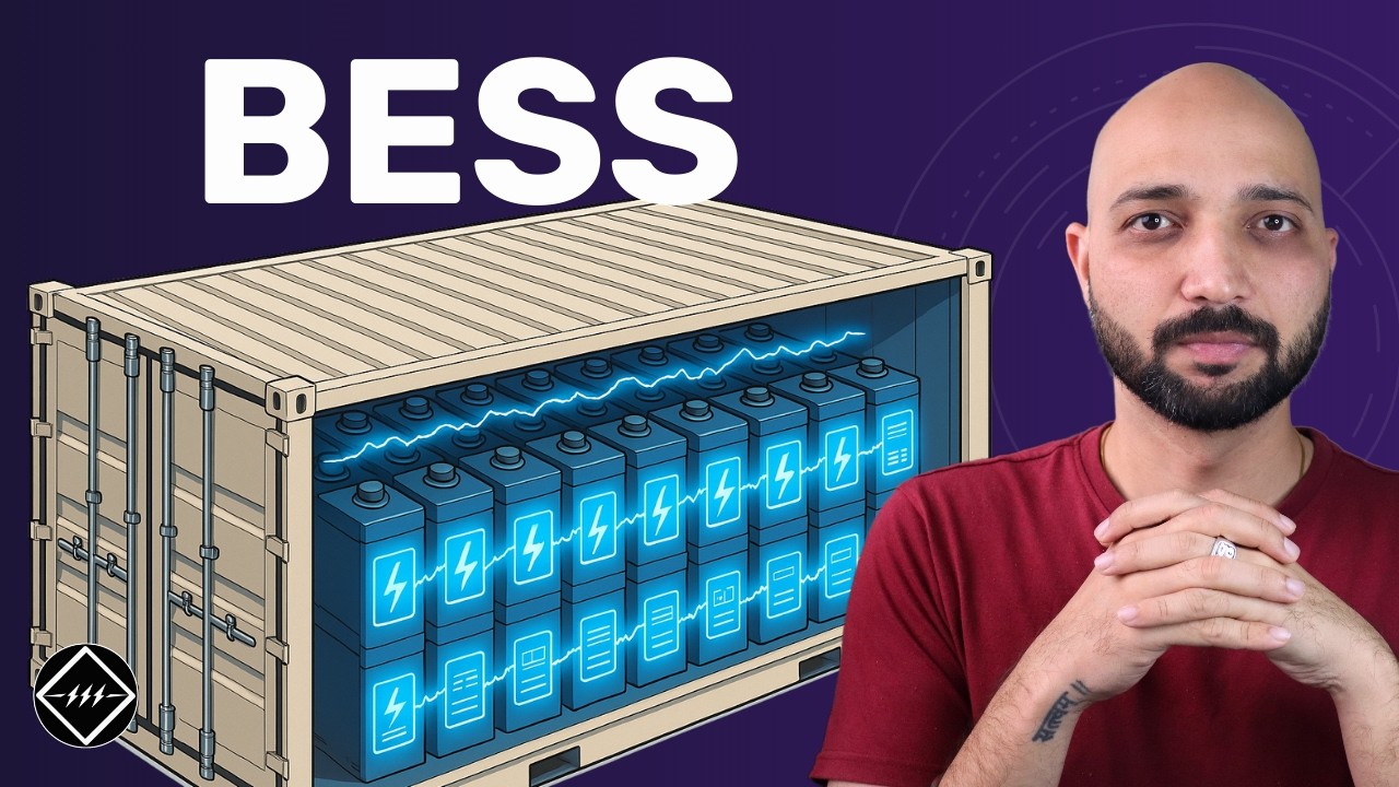
Battery Energy Storage System | BESS | Explained | TheElectricalGuy
An introductory guide on battery energy storage system. BESS system is used to store green energy and use it when needed. This offers a better energy storage solution for renewable energy. In this video you'll learn about what is BESS, components of battery energy storage solution and the locations where we can install it. 👩🏻💻 BESS Course - https://bit.ly/bess_course Actual BESS from Factory - https://youtu.be/GNmL-gBPe3g Videos you may find useful - Switchgear Basics - https://www.youtube.com/playlist?list=PL_Ht1_dWu2YzJWlrcvIcMkXEvedYWVjUa Technical Interview help - https://www.youtube.com/playlist?list=PL_Ht1_dWu2YzGlvdq155PMiS85qY-CRam #BESS #batterystorage #batterysolutions ⏰ Time Stamp 0:00 Intro 1:33 What is BESS 4:43 BESS Components 8:57 Locations of BESS 10:31 Benefits of BESS 13:00 BESS Challenges ---------------------------------------- 📚 Technical Books that I recommend - Electrical Machines, Drives And Power Systems - https://amzn.to/4jnDspS Switchgear Protection and Power Systems - https://amzn.to/4arP7jp Transmission and Distribution Electrical Engineering - https://amzn.to/4h2GRZJ Electrical Power Systems Quality - https://amzn.to/4gYS3q4 Basic Electrical Engineering - https://amzn.to/3Efrf6n More books recommendation here - https://courses.theelectricalguy.in/books Above links are affiliate links, meaning I may earn a small commission if you purchase through them at no extra cost to you. I only recommend books and gear that I have personally used and found valuable. Your support helps me continue creating content and sharing knowledge—thank you! =============================================== 📌 Lets connect online LinkedIn ➜ www.linkedin.com/in/gaurav-r-joshi Instagram ➜ https://www.instagram.com/the_electricalguy/ Facebook ➜ https://www.facebook.com/IamTheElectricalGuy/ =============================================== 🙋🏻 Who Am I? Hi, I’m Gaurav Joshi – an electrical engineer, teacher, and content creator with over 8 years of experience in the switchgear industry. I’ve had the privilege of working with renowned companies like Siemens and am currently with Schneider Electric. In my free time, I focus on creating valuable content for a growing community of 200k+ followers and teaching online to over 4k students worldwide.
Play Video
Play Video
03:41
EV Batteries: They’re Not All The Same
Underneath the hood of an electric vehicle is the car’s battery pack. That lithium-ion battery is where the car stores all its energy. In this video, Popular Science explores the most common battery types used today by automakers: NMC, NCA and LFP. While they might all look the same, there are some big differences between them. We explain how building batteries made from more abundant materials like iron, allows batteries to be more cost effective, more sustainable and more durable than batteries that rely on critical materials like nickel and cobalt. We partnered with @Our Next Energy (ONE) to show how lithium iron phosphate (LFP) is making a big difference in the future of electrification. Learn more at https://one.ai. Video presented by Our Next Energy. #electricvehicles #battery101 #EVBatteries #LithiumIronPhosphate #SustainableEnergy #EVTechnology #BatteryChemistries #EnergyDensity #CostEffective #Durability #PopularScience #GreenTransportation #CleanEnergy #Innovation #TechExplained #RenewableEnergy #OurNextEnergy #FutureOfMobility #Electrification #GreenRevolution #lfp #batterytechnology #futureofmobility #onebattery #arieslfp -- GET MORE POPULAR SCIENCE https://www.popsci.com E-mail newsletter: http://pops.ci/enews Facebook: https://www.facebook.com/popsci Twitter: https://www.twitter.com/popsci Instagram: https://www.instagram.com/popsci Flipboard: https://flipboard.com/@PopularScience Podcasts: https://www.popsci.com/popular-science-podcasts
Play Video
Play Video
01:57
Transformer Turns and Ratio Test | Technician Talk
Have you ever wondered what a transformer does? Transformers are used to change voltages ⚡ for different uses, and the turn ratio dictates the operation of the transformer and the corresponding voltage available. In today’s episode of #TechnicanTalk, Justin explains how we confirm the ratio accuracy of transformers in our testing. Learn more about the One Energy team: https://oneenergy.com/about-one-energ... To catch future Technician Talk videos, subscribe to our YouTube channel: https://bit.ly/2MmG4oD *********************************** One Energy is an industrial power company. We provide energy solutions, including Wind for Industry® and ManagedHVTM projects, to empower large commercial and industrial customers. To learn more: Visit OE’s Website: https://oneenergy.com/ Find OE on Facebook: https://www.facebook.com/oneenergywind/ Find OE on Twitter: https://twitter.com/oneenergywind Find OE on LinkedIn: https://www.linkedin.com/company/one-energy-enterprises-inc Find OE on Instagram: https://www.instagram.com/oneenergywind/ ******************************* This video was shot at One Energy’s headquarters at the North Findlay Wind Campus in Findlay, Ohio.
Play Video
Play Video
01:00
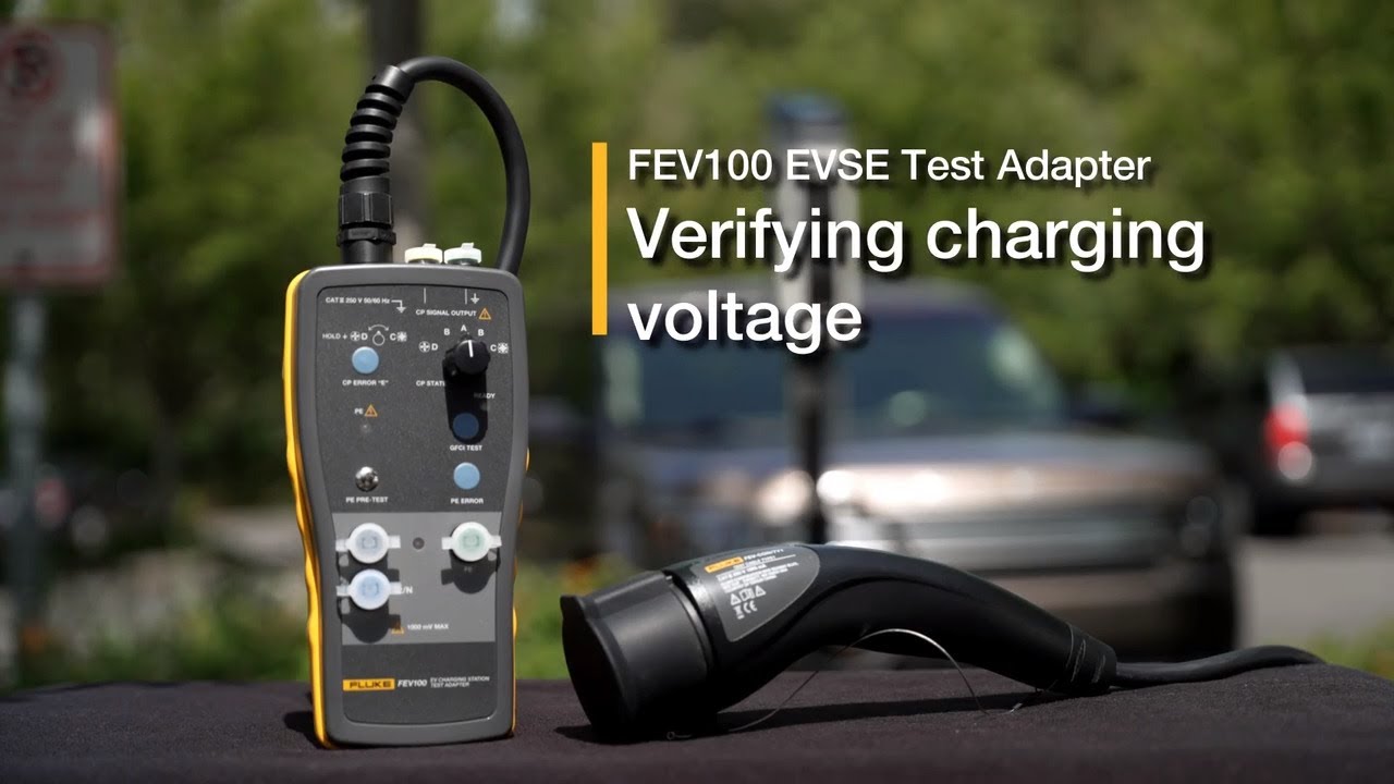
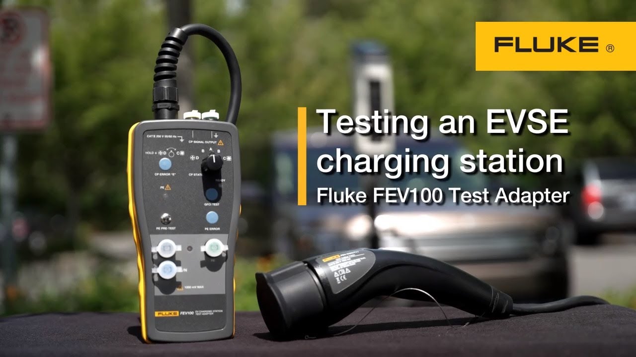
Fluke FEV100 EVSE Test Adapter | Verifying charging voltage
The FEV100 simulates control pilot charging states of an electrical vehicle, so you can verify the charging voltage using a digital multimeter. Product link: https://www.fluke.com/en-us/product/electrical-testing/installation-testers/fev100
Play Video
Play Video
01:21
Solar Safety Inspection with SMFT 1000
Learn more Follow Dutch solar safety inspector Remco de Mol as he uses the Fluke SMFT-1000 Solar Multifunction Tester to make his workflow more efficient. Solar inspectors need to do their job quickly and effectively, and the SMFT-1000 solar multifunctional tester makes their workflow easier. It does the tests needed and stores the data, eliminating the need for multiple testers or a laptop on site. Learn more: https://fluke.com/en-us/product/electrical-testing/best-solar-energy-industry-tools/smft-1000-pv-tester
Play Video
Play Video
02:28
How to test a charging station with the Fluke FEV100 Test Adapter
Simulate the presence of an electric vehicle to enable you to test the function and safety of an AC level 2 charging station. The test cable is the interface for cables of stations that have a Type 1 plug. Product link: https://www.fluke.com/en-us/product/electrical-testing/installation-testers/fev100
Play Video
Play Video
02:21
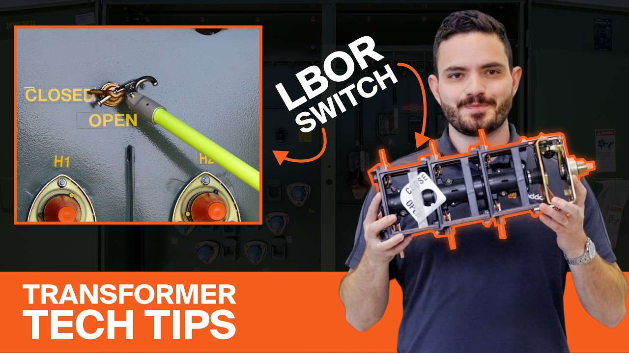
Transformer Loadbreak Switches Explained: 2-Position vs 4-Position
Learn how transformer loadbreak switches work in this simple, step-by-step guide. We’ll cover the difference between two-position and four-position load break switches, how they operate, and when each type is used in distribution transformers. Whether you’re an electrical engineer, lineman, utility worker, or contractor, this video will help you understand: - What a transformer loadbreak switch is - How 2-position switches work (ON/OFF operation) - How 4-position switches work (loop-feed operation) - How to safely operate a loadbreak switch using a hot stick 🔔 Subscribe for more transformer tips, electrical engineering guides, and power distribution tutorials. #transformer #energy #electrical Video Chapters: 0:00 Introduction 0:10 What is a Loadbreak Switch? 0:22 Two Types of Loadbreak Switches 0:30 Two-Position Switches (ON/OFF Operation) 0:55 Four-Position Switches (Loop-Feed Operation) 1:31 How To Operate a Loadbreak Switch
Play Video
Play Video
14:31
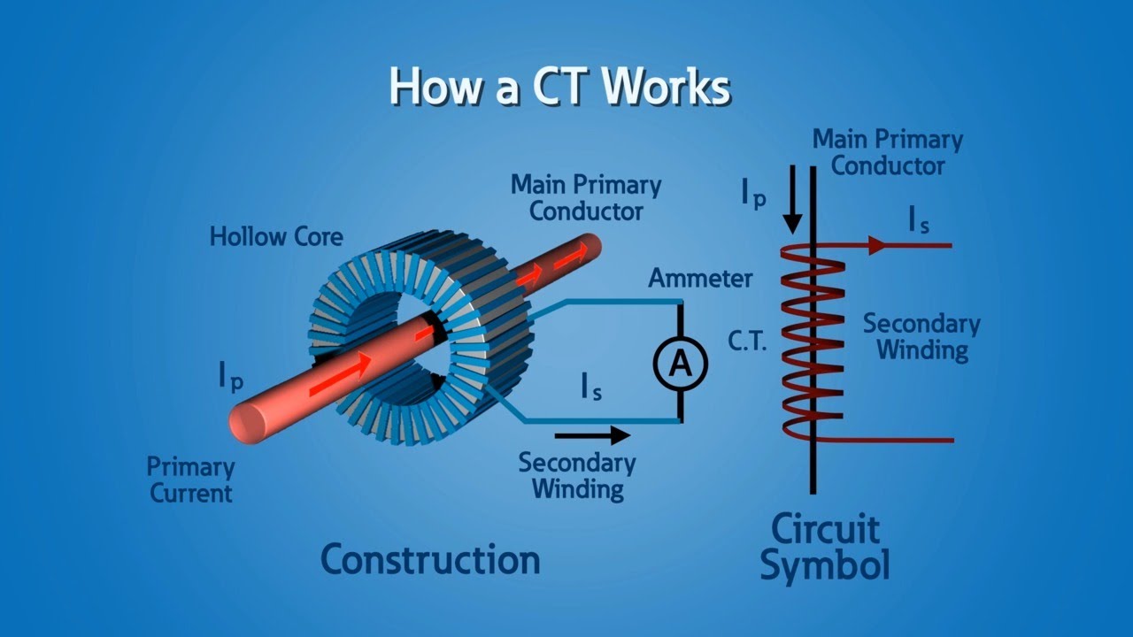
Current Transformers (CT)
Current transformers are used extensively in metering and circuit protection. Eaton's Power Systems Experience Center is the ideal place to learn how to properly apply CTs considering accuracy, types, safety, temporary and permanent applications.
Play Video
Play Video
12:38
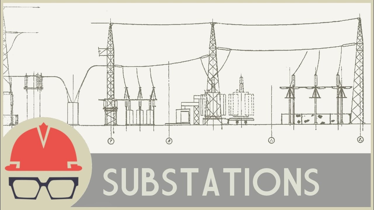
How Do Substations Work?
Untangling the various equipment you might see in an electrical substation. In many ways, the grid is a one-size-fits-all system - a gigantic machine to which we all connect spinning in perfect synchrony across, in some cases, an entire continent. On the other hand, our electricity needs, including when we need it, how much we need, and how reliably it should be delivered vary widely. Substations play a critical role in controlling and protecting the power grid. Watch this video and the entire Practical Engineering catalog ad-free on Nebula: https://go.nebula.tv/practical-engineering -Patreon: http://patreon.com/PracticalEngineering -Website: http://practical.engineering Writing/Editing/Production: Grady Hillhouse Animation: Stephanie White, Connor Claver, Dayan D’Aniello Tonic and Energy by Elexive is licensed under a Creative Commons Attribution License Source: https://www.youtube.com/watch?v=U6fBPdu8w9U This video is sponsored by NordVPN.
Play Video
Play Video
00:57
Substation Transformer Overview: ATCs, Throats, Closed Couple Switch | Maddox
View the options for your Maddox substation transformer: - Throat - ATCs - Gauges w/ contacts - Fans - Top mounted bushings - Close coupled switch Get a quote today: https://www.maddox.com/products-and-services/substation #electrical #electrician #energy #transformer #substation
Load More
bottom of page